Rear Turn Signal Conversion
Running lights, brake lights, and signal lights for $20
(Plus the cost of new rear sigs, but you were going to buy
them anyway, weren't you?)
If you want more visibility for your rear end, especially if you've replaced
the stock brick tail/brake light with either the Mistry or Billski mod,
one solution is to convert your rear turn signals so that they function
as tail lights, brake lights, and turn signals all in one. Motorcycle specific
modules to do this cost $40-$100+. There's another way.
Author's note: While this was written specifically for the Honda Shadow Spirit 750, the concepts will work for pretty much any bike to which you care to apply them. You'll need to know the specifics of your wiring harness colors, and whether or not bullet connectors are used in the harness (as opposed to modular plugs or some other form of connector) Also, it is essential that you convert to 1157 (dual-filament) style bulbs with RED tail light lenses. As mentioned below, amber rear running and brake lights are illegal in most states, but they would also take away from the safety factor you're trying to accomplish with this mod, since a bright yellow light doesn't say, "STOP! " |
 |
You'll need
| QTY |
Part |
Part Number |
Source |
Cost |
| 1 |
Hoppy Trailer Tailight converter |
|
Wal-Mart, AutoZone |
$10 - $12 |
| 1 |
Tridon heavy duty flasher |
EL-12 or EL-12C |
AutoZone |
$6 - $8 |
| 10 |
Male & female insulated bullet connectors |
NA |
Wal-Mart, AutoZone, Radio Shack |
$2 - $3 |
| 2 |
Female insulated spade connectors |
NA |
|
pennies |
| 1 -2 feet |
16 or 18 AWG automotive primary wire (16 AWG preferred) |
NA |
Wal-Mart, AutoZone, Radio Shack |
$2 - $4 |
You will also need to change out your rear turn signals to dual-filament (1157-type
bulb) units with RED lenses. In most, if
not all states, it is illegal to have amber rear running or brake lights.
Here is what I used (credit to IOWARIDER for suggesting them):
| Dual filament turn signals (these are nice ones) |
|
|
| Red Lenses: |
|
|
| Relocation bracket (optional, I didn't use it) |
|
381-518
or 19-096 |
I strongly recommend that you read through these instructions before starting.
I've tried to put everything in logical, step-by-step order, but you still need
to understand the whole sequence before you start.
The following instructions allow the mod with NO CUTTING of stock wires except
for those for the flasher. This lets you return to stock quickly and easily
if you ever want to. The connectors are crimp-ons. The instructions assume that
you know to strip the wire ends of insulation when putting on a connector and
that you will crimp them using either wire pliers or the shade-tree wrench's
best friend, Visegrips. They also assume you'll tape or shrink tube where the
wire enters the connector OR ANY EXPOSED METAL. I prefer shrink tube.
|
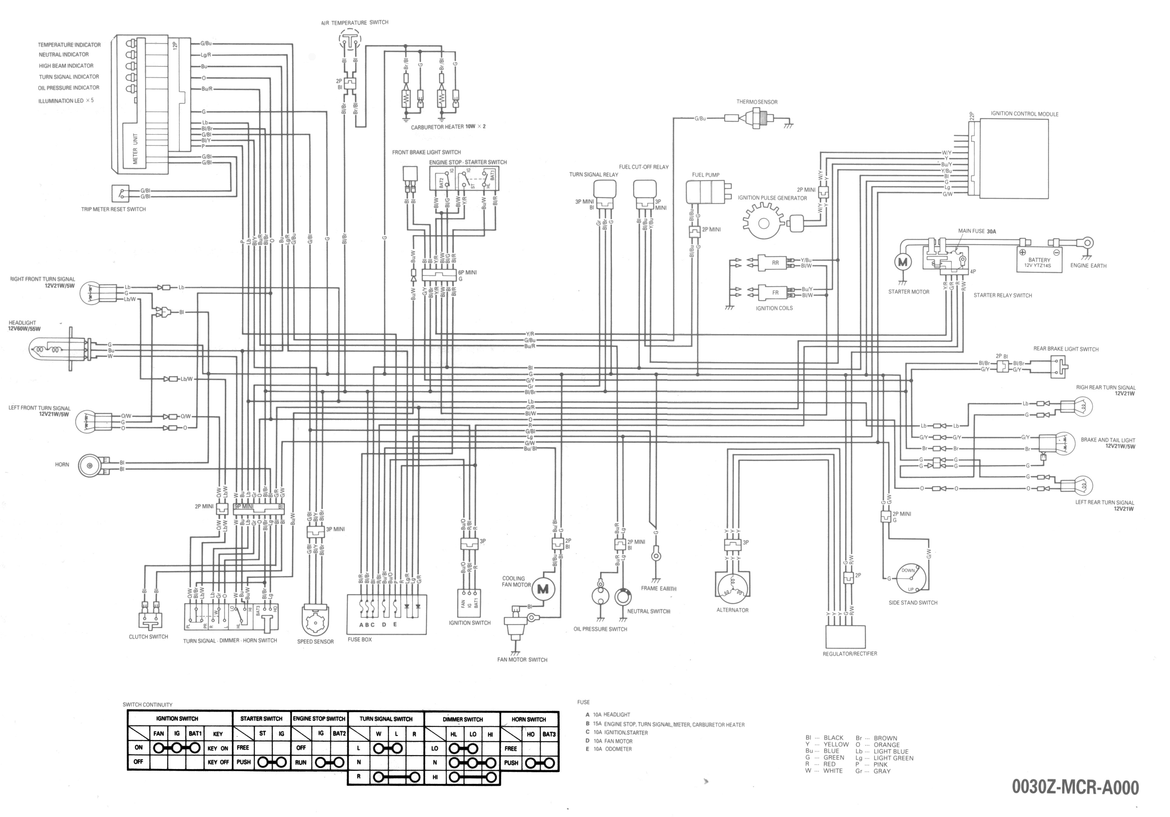
Here's a schematic of what you'll be wiring up: |
 |
|
|
On the Spirit a green wire is the ground wire throughout
the wiring harness. |
|
|
1. Remove your seat.
1.1 Unscrew and remove the two allen bolts on the side (the ones that
hold the passenger strap in place), slide back, lift up.
2. Remove the rear fender
2.1 Unscrew the two shock bolts. Unscrew the little mushroom-shaped
bolt on top of the fender. Unscrew the bolt that holds the seat-mount bracket
in place.
2.2 Carefully lift the fender from between the frame arms. Turn the
fender upside down. Lay a towel over the frame arms and put the fender down
between them. This gives you access to the rear signals and wires. Be careful.
It is easy to scratch your paint at this step.
3. Remove the stock signals
3.1 Under the seat is a plastic boot with a bunch of bullet connectors
in it. This is where the rear end lights connect to the main wiring harness.
In the boot, there's also a nexus point where several green ground wires all
plug into the same place.
3.2 Disconnect your turn signals, but pay attention to the colors of
the wires going to the left (Orange) and right (Light Blue) signals and a ground
(Green) wire for each. You might want to label them on the wiring harness side.
A little masking tape flag works well for this.
3.3 Starting from the seat end (where you've disconnected from the main
harness) work the wire bundles for each signal out until they are hanging free
at the signal mount. Pay attention to the path the wire bundle follows, because
you want to route the wires from the new signals through the same path. This
will make sure you don't have any wires that will be rubbed by the tire.
3.4 Unscrew the nut holding the turn signal to the mounting bracket
and pull the signal loose from the rubber grommet. Work the wire bundle through
the grommet.
4. Install the new signals
4.1 With the signals suggested above, use a bolt to attach them to either
the stock brackets (I left the rubber grommet in place) or to the relocation
bracket suggested above. Use appropriately sized washers on either side. The
stock rubber grommet will provide some vibration dampening, but makes it a little
difficult to tighten them enough to have correct alignment, but not so tight
you've distorted the rubber. I just played with it until they were tightened
just right.
4.2 Run the wire bundle through the other hole in the rubber grommet
and force it to make a very tight turn so that it stays as close as possible
to the inside of the fender. This helps avoid tire rubbing.
4.3 Route the new wire bundle to the front of the fender using the same
pathway as the stock wire bundle.
4.4 You should have three wires coming out of the new turn signals.
One of these is the ground wire. If they are not marked, use a continuity meter
to figure out which is the ground.
4.5 If your new lights only have two wires, and you really have dual-filament
lights, then the ground is through contact with the frame via the mounting bolt.
This simplifies the identification process. If the rubber mounting grommet is
still in place, you may not get sufficient ground connection through the frame.
You may have to connect a wire from the mounting bolt to the frame.
4.6 To figure out which is the ground wire if you have 3 wires, check
continuity between the wires, one pair combination at a time. The bulb should
be in the socket for this. The wire that has continuity to both the others is
the ground wire. The two that do not have continuity between them are the filament
wires.
4.7 You may have to connect up a 12V or 9V battery (I use my auto battery
charger set to the 2 AMP level) to figure out which wire goes to the tail light
filament and which goes to the brake/signal filament. Connect the negative battery
(charger) terminal to the ground wire (or light housing if you've only got two
wires.) Touch the positive battery (charger) terminal to each of the other wires,
one at a time. The bright one will be the brake/signal filament wire. LABEL
THEM.
4.8 Install male bullet connectors on each of the wires coming from
your new turn signals. I had to cut off the HD style connectors that came with
the lights first. If you want to avoid the use of some of the pigtail connections
that will be called for later, crimp the right and left taillight wires into
a single bullet connector and crimp both the right and left ground wires into
a single bullet connector.
4.9 Locate the Brown tail light wire and Green/Yellow (green wire with
yellow band marks) brake light wire in the wiring harness boot. Label them if
you want to.
5. Prepare the converter
5.1 Figure out where the Hoppy converter will live. I just let mine
sit on top of the battery cover. Actually, it sits on top of the spark module
that sits on top of the battery cover. It's a good idea to fix it in place with
double-sided tape. Cut all the wires coming out of the converter to a reasonable
length, but make sure to leave enough slack that you can move the converter
out of the way to get to the battery once it's all connected up.
5.2 The converter is labeled "car side" and "trailer
side". For our purposes, this is "wiring harness side" and "light
side." There are four wires going into the wiring harness side and three
wires coming out of the light side. Install male bullet connectors on the wiring
harness side, and female bullet connectors on the light side.
6. Hook 'em up
6.1 The turn signal connectors in the wiring harness boot are already
empty (from when you disconnected your stock lights), so begin by plugging the
right and left turn signal wires coming from the wiring harness side of the
converter into the right and left connectors in the boot. Plug the right and
left turn signal wires from your new lights into the right/brake and left/brake
connectors on the wires coming from the light side of the converter.
6.2 Make three 'Y' pigtails using one male bullet connector, two female
bullet connectors, and two short pieces of automotive primary wire for each
pigtail. To do this put female connectors on one end of each piece of wire then
twist together the other ends and insert them into the single male connector.
6.3 Locate the Brown wire for the taillight in the harness boot and
disconnect it. Plug the male end of one pigtail into the wiring harness and
plug the main taillight wire into one side of the Y. Plug the "taillight"
wire on the wiring harness side of the converter into the other side of the
Y. What we've done is bypass the converter for the main taillight.
6.4 Locate the Green/Yellow brake light wire in the harness boot and
disconnect it. Plug your third pigtail into the brake light connector in the
boot. Plug the main brake light wire into one side of the Y. Plug the "brake
light" wire on the wiring harness side of the converter into the other
side of the wire. Now we've bypassed the converter for the main brake light.
| The use of pigtails in steps 6.3 and 6.4 might
seem like over-engineering. But, it serves two purposes. As mentioned, it
lets you avoid cutting any stock wires. In addition, it creates a fail-safe.
If the module quits working for any reason, your main tail and brake light
are still connected directly to the bike's wiring harness. You can do without
turn signals for awhile, but not without tail and brake lights. |
6.5 Plug your second pigtail into the taillight wire on the light side
of the converter. Plug the taillight wires from your new turn signals into the
pigtail. Note: You don't need this pigtail if you used one connector for both
taillight wires from the new lights as mentioned in step 3 above.
6.6 If you have ground wires for your new turn signals, make another
pigtail and plug the male end into the ground wire nexus in the wiring harness
boot, then plug the ground wires from the signals into the female sides of the
pigtail. Note: You don't need this pigtail if you used one connector for both
ground wires from the new lights as mentioned in step 3 above.
7. Upgrade your flasher
| 7.1 Pull off the right side cover and
locate the flasher unit. It's a small block-shaped module. See the attached
page from the shop manual. (The flasher is called the Turn Signal Relay
in the manual.) There are three wires going into the connector for the flasher.
One of these, the Green, is (guess what!) a ground wire and not needed for
the new, heavy-duty flasher. Snip the other two wires. I tried to leave
enough tail on the flasher connector so that I could repair them later if
necessary. You can put the stock flasher with its connector back in place
if you want, or you can disconnect it. Whichever. Put female spade connectors
on the wires you cut. Plug one spade connector on each blade terminal of
the new flasher. The flasher is polarity neutral. It doesn't matter which
wire goes on which terminal. I used a cable tie to fasten the new flasher
to one of the vertical frame members. Just do it so that it fits and is
hidden behind the side cover when you put it back on. |
|
8. You're done!
8.1 Test, debug if necessary, and button things back up. You're ready
to ride!