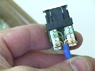
| At each wall
outlet, the CAT 5 UTP is terminated in a Superior Modular brand 8 position RJ45 type data
jack configured to 568B pinouts. While 568B is more
prevalent for commercial data applications, the 568A
pinout scheme is actually more conducive to a
combined voice & data installation in the home.
In this install, 568B was used and the pinout scheme
was compensated for at the incoming service line.
Note that a standard RJ11 type plug used by phones
will fit in a RJ45 jack, allowing the jacks to be
used for voice or data at the home owners choice. |
 |
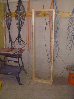 |
An equipment
rack was built from 2 x 4s and scrap lumber to hold
the patch panel during termination. After
termination, the distribution points were permanently
mounted on the wall for greater stability and
protection to the components, and to free up floor
space. |
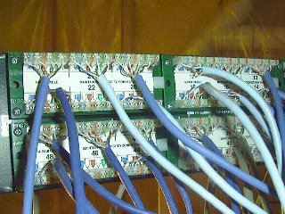
| Every cable
that runs to a jack on a faceplate is terminated on a
Superior Modular brand 48 port Category 5 patch
panel. For faceplates with two jacks, the runs were
punched down so that the top jack on a faceplate
terminates in a top jack on the patch panel The
bottom jacks were done likewise. This picture shows
the back of the patch panel before the wires were
organized and bundled together. Note that I was
working with wire samples provided for free, so
limited color coding of the runs was done, although
this would be desirable. |
 |
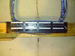 |
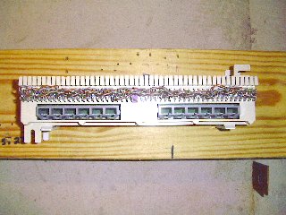
This is the 48
port patch panel with the cables organized and
dressed. It is attached to the wall using a hinged
rack-mount bracket. |
| This is the
distribution block for the phone lines. It consists
of a 66 block type punchdown pre-wired to 568B pinout
RJ45 outlets. It is manufactured by Hubbell. The outlets are daisy-chained
together using individual pairs from a piece of CAT 5
cable. Starting from the left at position one of the
block, white/blue is punched down on position 1, 5,
9, etc. White/orange is punched down on position 2,
6, 10, etc. The pattern is continued for white/green
and white/brown. This block allows for up to 12 phone
extensions, each capable of handling 4 phone lines.
Additional blocks could be daisy chained to this one
to provide for more extensions. |
 |
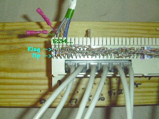 |
Incoming line
one is punched down on position 1 of the block. In
the 568B pinout scheme, this corresponds to the
center 2 pins of the phone plug, which is just where
your phone equipment expects it. Your phone equipment
expects line two be split on either side of the
center pins. This corresponds to pair three
(white/green) in the 568B scheme, so incoming line
two is punched down on position 3 of the block. If
the 568A pinout scheme was used, line two could be
punched down on position two of the block. The two
red crimp connectors above the block are where the
security system connects to line one before it is
terminated on the block. |
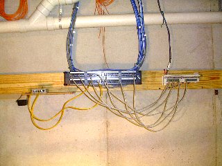
| This photo
shows the communication distribution installation. In
the center is the patch panel where all the runs to
the faceplates terminate. On the right is the phone
distribution block. Patch cords (grey) are used to
connect from the phone block to any port on the panel
where a phone extension will be plugged into a
faceplate jack. On the left is a small Ethernet hub.
Patch cords (yellow) are used to connect the hub to
any port on the panel where a PC will be plugged into
a faceplate jack. |
 |
 |
The video
distribution center. The incoming CATV line is
terminated in a 22 dB amplifier with four outputs.
Each output is connected to an 8 position splitter.
The coax runs are connected to the splitters for
distribution of the CATV signal throughout the house.
This set up can be flexed to handle multiple video
inputs or Internet access via cable modems. |
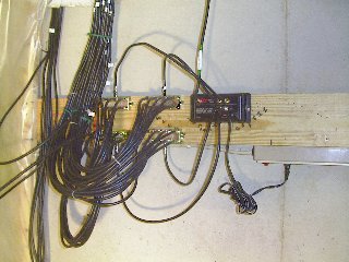
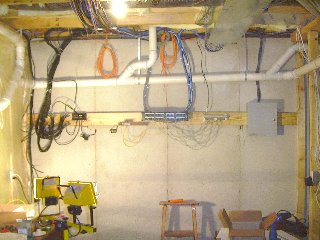
| The whole
shebang. Security
wiring terminates in the grey box on the right. The
orange cables looped above are the fiber optic cables
installed for future termination and use.
|
 |