| Communications Cables | Revised: 08/22/99 20:08 |
| Residential Installation - Prewire | Reason for Revision: Add additional photos; modify text. |
Photos on this page and on the one titled "Termination" are from an installation in a new-construction residence. The house, two stories with basement, totalled approximately 4,500 finished square feet.
The work was performed in accordance with the latest proposal for the highest level of a TIA/EIA 570 install, i.e., two points of presence in each room, two 4 pair CAT 5 cables, two RG-6 Quad shield cables, and two 62.5 multimode fibers to each point of presence. Fiftyfour single-gang boxes were used. Three thousand feet of CAT 5 cable, 3,000 feet of RG-6, and 1,500 feet of 2-fiber zipcord cable was star wired to a single point in the mechanical area of the basement. The average run length was around 60 feet.
Five people participated in the install:
Dave Barnett, RCDD
Jordan Barnett, go-fer
Jason Krauskopf (RCDD to be)
Eric Nelson, Master Electrician
Jim Starnes, Engineer
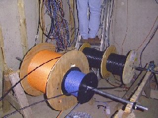 |
Wire was paid off from improvised cable stands. The two RG-6 coax, fiber, and one of the CAT 5 cables is shown. The second CAT 5 cable is being pulled from a coil on the floor. For each run, the five cables were taped together at the leading end and pulled to the outlet area. After placement in the outlet box, excess cable was pulled back to the termination point (approximately where the person on the ladder is in this photo.) The run of cables was tied together periodically along its length, labeled, and the ends were mounted on a 2x6 board for later termination. |
| This photo shows Eric using plastic 1/2 inch Romex staples to secure a vertical run in a stud cavity. Care was taken not to crimp, compress, or nick cables during stapling. In some stud and joist cavities it was virtually impossible to maintain recommended 6 inch spacing from the electrical wiring, but in all cases, the datacom wiring was placed perpendicular to the electrical wiring to minimize any influence due to proximity. | 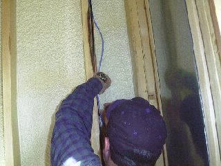 |
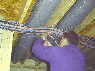 |
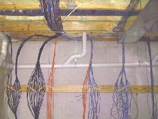
Here Jim adjusts cable bundles in wire rack devices attached to joists in the unfinished part of the basement. The brackets were improvised from retail-display peg board hooks and nailed in place every 4 feet along the run, which extended the entire width of the house. Note the wire ties around the bundles that make up individual runs. Where necessary, bundles were routed from this main "trunk" into the joist cavities to reach locations on the other side of the house. Plastic 1/2 inch Romex staples were used to secure the cables in the joist cavities as in the picture of the vertical run, above. |
| At the outlets, CAT 5 and fiber cables were routed to one box and the RG-6 cables to another. In many cases, the two boxes were adjacent to each other, but were sometimes separated, depending on the room function and layout. The fiber will not be terminated until needed in the future, so it will remain coiled in the box until needed. Although it appears from the viewing angle of this photo that the staple causes a sharp bend in the cables, in fact, all bends maintained minimum recommended radii. | 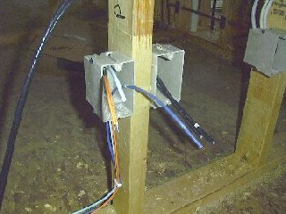 |
 |
The cables are fanned out on a 2 x 6 awaiting termination. Each outlet run was numbered during installation. These numbers are recorded on the fanout board behind the individual cables. Note the bundle to the far right. This is the security wiring, installed after we finished the other communication wiring. |